

 02-26-2021 |
  Hits:963
Impact strength is often used to evaluate the ability of materials to resist impact or to judge the brittleness or toughness of materials. It is an important performance index of plastic materials in engineering application. It reflects the ability of different materials to resist the damage caused by high-speed impact. In order to truly reflect the impact resistance of materials, so as to better study the material properties of different plastics, design related products or control the quality of products, it is necessary to carry out impact resistance test on plastics, that is, to measure the impact strength of materials under impact load. At present, the commonly used test methods are cantilever beam impact method and simply supported beam impact method. First of all, according to GB / t1843 and iso180 to introduce the impact test method of plastic cantilever beam.
1、 Scope of application and precautions
1. This method is suitable for the determination of impact strength of plastic cantilever beam under certain conditions.
2. This method is used to study the impact behavior of specified types of specimens under standard conditions and to evaluate the brittleness and toughness of specimens under test conditions.
3. This method is applicable to the following materials:
① Rigid thermoplastic molding and extrusion materials, including filled and reinforced composites, and unfilled materials; rigid thermoplastic sheet;
② A rigid thermosetting molding material, including a filling and reinforcing composite material; a rigid thermosetting sheet, including a laminate;
③ Fiber reinforced thermosetting and thermoplastic composites, including unidirectional or non unidirectional reinforcements such as felt, fabric, textile roving, chopped strand, composite reinforcement, untwisted roving, ground fiber and sheet made of prepreg;
④ Thermotropic liquid crystalline polymer.
4, this method is usually not suitable for rigid foam materials and sandwich structure materials containing foams. Notched specimens are usually not suitable for long fiber reinforced composites or thermotropic liquid crystalline polymers.
5. The samples required for this method are those molded to the selected size, those machined from the middle part of the standard multi-purpose sample (see GB / T 11997), or those machined from finished or semi-finished products, such as molded parts, laminates, extruded or cast plates.
6. The test results of specimens prepared by different notches or different methods are not comparable. Other factors, such as the energy of the device, the impact speed and the state adjustment of the sample, will also affect the test results. Therefore, when data comparison is needed, these factors should be carefully controlled and recorded.
2、 Test principle
The energy absorbed by the specimen is measured when the specimen is supported as a vertical cantilever beam by a pendulum with known energy. For notched specimens, the distance from the impact line to the center line of the notch is fixed (see Figure 1).

Figure 1 Schematic diagram of impact of fixture, sample (notch) and impact edge
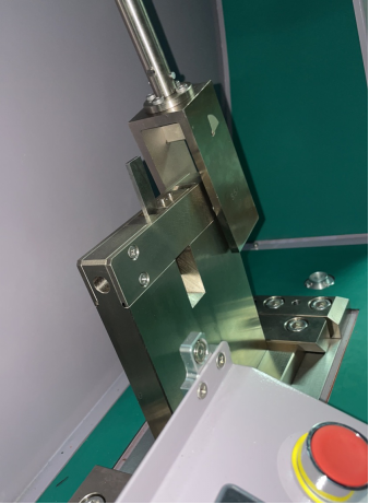
3、 Test equipment
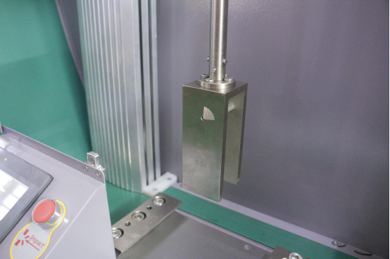
Impact test hammer of cantilever beam
Plastic pendulum impact testing machine is a testing instrument to test the impact resistance of non-metallic materials such as plastic, nylon, rubber, FRP, composite plastic pipes, electrical insulation materials under dynamic load. According to the display mode, the machine can be divided into pointer type, liquid crystal type and microcomputer type. It is easy to operate and has high working efficiency. It can be used for simple beam test, cantilever beam test and tensile impact test. The support is easy to adjust and replace and has strong applicability. It is an indispensable testing instrument for hard plastic manufacturers, plastic pipe manufacturers, quality inspection units and scientific research institutes .
4、 Sample preparation
1. Sample preparation
① Molding and extrusion materials
The material shall be prepared according to the relevant material standards. If there is no such standard or otherwise specified, the sample shall be directly molded or injected according to the corresponding standards of GB / T 9352, GB / T 17037.1, GB / T 5471 or ISO 10724-1, or machined from the sheet of material molded or injected. The sample can also be cut from the multi-purpose sample conforming to GB / T 11997 a.
② Plate
The specimen shall be machined from sheet metal in accordance with ISO 2818, using type a notch as far as possible. During the test, the machined surface of the notchless specimen shall not be in the tensile state.
③ Long fiber reinforced material
Plates shall be made according to ISO 1268 or other standard or agreed methods. The specimens shall be machined in accordance with ISO 2818.
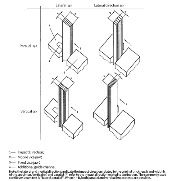
Fig. 2 nomenclature of impact direction
④ Inspection
The specimens shall not be warped, the relative surfaces shall be parallel to each other, and the adjacent surfaces shall be perpendicular to each other. All surfaces and edges shall be free from scratches, pitting, dents and flash.
Whether the sample meets the above requirements shall be visually inspected with ruler, square and flat plate or measured with micrometer. If one of them fails to meet the requirements, the sample shall be scrapped or processed to meet the requirements before the test
⑤ Processing of notch
Notches shall be prepared in accordance with ISO 2818 machining method. The shape of the cutting teeth can cut the sample into the notch shape shown in Fig. 3, and the profile of the cutting teeth should be at right angles to its main axis. The shape of the notch should be checked regularly.
If the material to be tested is specified, molded notched specimens can be used, and the test results are not comparable with those of machined notched specimens. The shape of the notch should be checked regularly.
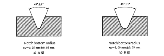
Figure 3 notch type
2. Anisotropic material
Some plates may have different impact properties with different directions. For this kind of plate, a group of samples should be cut parallel and perpendicular to a certain characteristic direction. The characteristic direction of the sheet can be observed visually or inferred from the production method.
3. Shape and size
① General rules
The sample size is shown in Table 1. If necessary, the length of the specimen can be reduced symmetrically to 63.5 mm. The longitudinal direction of the notch is always parallel to the thickness H.
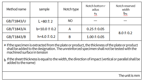
Table 1 method name, specimen type, notch type and notch size
② Molding and extrusion materials
According to table 1 and figure 3, one type of notch shall be used for the specimen, and the notch shall be in the middle of the specimen. The preferred notch type is type A. in order to obtain the information of notch sensitivity, the specimens with type A and type B notch should be tested.
③ Plates, including long fiber reinforced materials
The recommended thickness h is 4mm. If the specimen is cut from the plate or component, its thickness shall be the same as the original thickness of the plate or component, not more than 10.2mm at most.
When the thickness of the sheet is uniform and only contains one kind of reinforcement with regular distribution, when the thickness is greater than 10.2 mm, it is machined from one side of the sheet to 10.2 mm ± 0.2 mm. In order to avoid the influence of the surface, the original surface of the sample should be in the tensile state.
During the test, the impact direction of the side of the sample is parallel to the plane of the plate. Only when h = b = 10 mm, the test can be carried out parallel or perpendicular to the plane of the plate.
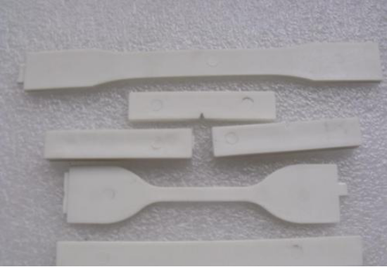
Table 1 method name, specimen type, notch type and notch size
② Molding and extrusion materials
According to table 1 and figure 3, one type of notch shall be used for the specimen, and the notch shall be in the middle of the specimen. The preferred notch type is type A. in order to obtain the information of notch sensitivity, the specimens with type A and type B notch should be tested.
③ Plates, including long fiber reinforced materials
The recommended thickness h is 4mm. If the specimen is cut from the plate or component, its thickness shall be the same as the original thickness of the plate or component, not more than 10.2mm at most.
When the thickness of the sheet is uniform and only contains one kind of reinforcement with regular distribution, when the thickness is greater than 10.2 mm, it is machined from one side of the sheet to 10.2 mm ± 0.2 mm. In order to avoid the influence of the surface, the original surface of the sample should be in the tensile state.
During the test, the impact direction of the side of the sample is parallel to the plane of the plate. Only when h = b = 10 mm, the test can be carried out parallel or perpendicular to the plane of the plate. 4. Number of samples
Unless otherwise specified in the material standard under test, a group of samples shall be 10. When the coefficient of variation (see ISO 2602) is less than 5%, five samples can be tested.
If laminates are tested in both vertical and parallel directions, 10 specimens shall be tested in each direction.
5. State regulation
Unless otherwise specified in the material standard, the test shall be conducted according to GB / T 2918 at 23 ℃ and 50% relative humidity for at least 16 h, or according to the conditions negotiated by relevant parties. The state adjustment time of notched specimen should be calculated after notching.
5、 Test procedure
1. The test shall be carried out in the same environment as the condition adjustment, except for other conditions agreed by relevant parties, such as the test at high or low temperature.
2. Measure the thickness h and width B in the middle of each specimen or the remaining width BN of notched specimen to the accuracy of 0.02 mm. When the sample is injection molded, it is not necessary to measure the size of each sample. As long as the dimensions listed in Table 1 are ensured, only one specimen in a group can be measured. When using the multi-mode cavity mold, ensure that the size of the sample in each cavity is the same.
3. Determine whether the testing machine has the specified impact speed and appropriate energy range, and the energy absorbed by the impact specimen should be within the range of 10% to 80% of the pendulum nominal energy. If more than one pendulum meets these requirements, the one with the highest energy should be selected.
4. The friction loss and corrected absorbed energy are determined according to GB / T 21189.
5. Lift and lock the pendulum, install the sample as shown in Fig. 2, and note that some plastics are sensitive to the clamping force. When testing such materials, the clamping force shall be standardized, and the size of the clamping force shall be indicated in the test report. The clamping force can be controlled by a calibrated torque wrench or a pneumatic or hydraulic device on the screw tightened by the vice. When testing notched specimens, the notch should be on the side of the impact edge of the pendulum.
6. Release the pendulum, record the impact energy absorbed by the sample, and correct the friction loss. 7. Name the four types of shocks with the following characters:
C -- complete failure: the specimen is broken into two or more sections.
H -- hinge failure: a kind of incomplete failure in which the specimen has no rigid thin skin.
P -- partial failure: incomplete failure except hinge failure.
N -- no damage: no damage, only bending deformation, stress whitening may occur.
6、 Calculation and expression of test results
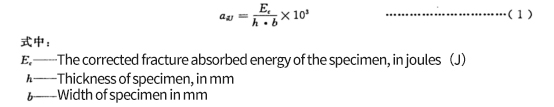
1. Notchless specimen
The notchless impact strength AIU of cantilever beam is calculated according to formula (1), unit: kJ / m2:
2. Notched specimen
The cantilever impact strength ain of notched specimen is calculated according to formula (2), in kJ / m2

3. Statistical parameters
Calculate the arithmetic mean value of the test results. If necessary, calculate the standard deviation of the mean value according to the method given in ISO 2602. When a group of specimens have different types of failure, the number of relevant types of tests should be given and the average value of each type should be calculated.
4. Significant number
Calculate the arithmetic mean of a group of test results and take two significant figures.